
DESIGN AND DEVELOPMENT OF ANTHROPOMORPHIC ROBOTIC HAND:
Group Members:
Fernandes Keith Infantus Miguel.
Gandhi Jayesh.
Kumbhar Gunjiker Ajay Balaram.
Landge Shahid Sadik.
Project Guide:
Dr. B. S. Manohar Shankar.
Introduction:
The human's ability to interact with the world for crafting, exploring and even convey emotions is one defining human characteristic that has inspired scientist and inventors for centuries. One of the results of such inspiration is the field of robotics, which aims to integrate computer science and engineering to replicate or substitute human actions. Robot is any automatically operated machine that replaces human effort.
Inception of its development was to majorly serve the industrial world in early 60s, Robotics further emerged Medical high-precision systems, prosthetics, in research to study the structure and function of the humans. The new generation of robots is expected to safely and dependably co-habitat with humans in homes, workplaces, and communities, providing support in services, entertainment, education, healthcare, manufacturing, and assistance and development of robotic arm is necessary for to achieve it.
Technically, robotic arm is a type of mechanical arm usually programmable with functions similar to human arm. In robotics the main component is end effector, a typical end effector is a gripper to pick, place and hold different objects. Some of other common end effector include deburring tools, cutting tools and welding equipment. But the most robust and dexterous end effector is a robotic hand.
Problem Statement:
It is not possible for a human to carry out several tasks on his/her own due to certain risks involved in it. So, instead of compromising on human life, a robot can be employed to perform these activities. A robot, as compared to a human, is superior in terms of accuracy, speed, working long hours and can work in almost any environment.
The robotic hands currently employed in industries use high end technology and complex design, which make them expensive and demand high maintenance. These challenges limit the extensive use of robotic hand in industries.
Thus, the following is proposed:
=>> To design an anthropomorphic robotic hand with major focus on structural design which is easy to operate and cost effective.
=>> To develop a microcontroller based five fingered robotic hand with a simple and minimal control strategy to grasp different objects.
Design of Robotic Hand:
ITERATION 1:
- The finger consist of 3 links, 3 pulleys and pins to connect the parts together.
- The thumb consists 2 links and pins to connect the parts together.
- The finger and thumb holders hold the finger and thumb respectively.
- Palm holds the thumb holder and finger holder.
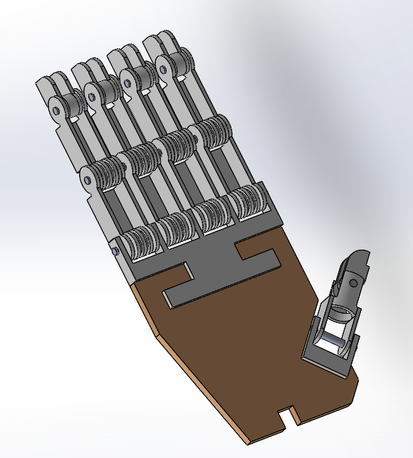
Fig 1: CAD Model of Iteration 1.
Drawbacks of Iteration 1:
- The links of the finger and thumb are weak, bulky and lacked proper functionality.
- Also it has complex pulley design.
- The thumb and finger holder contained less shear area towards the top and bottom side of the holders which could result in shear failure.
ITERATION 2:
- The revised finger consists of 3 links, 2 pulleys and pins to connect the parts together.
- The revised thumb consists of 2 links, 1 pulley and pins to connect all parts together.
- Link 1 of both finger and thumb is integrated with a pulley and together form a single part, reducing the number of pulleys by 1.
- The links are stronger and have locking mechanism and also have appealing appearance.
- Design of pulley is simplified.
- Both the thumb and finger holders were provided with more shear area to avoid failure.
- The palm is coupled with the motor holder.
- Palm is provided with string guides.
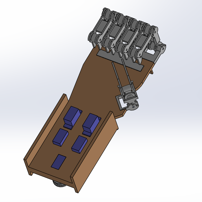
Fig 2: CAD Model Of Iteration 2.
Drawbacks of iteration 2:
- During prototype of iteration 2 it was observed that it took a lot of time for assembly of the parts.
- Servo motors couldn’t be removed for repair or replacement once mounted.
- Since the connections were done on breadboard, it took a lot of space and made connections complex.
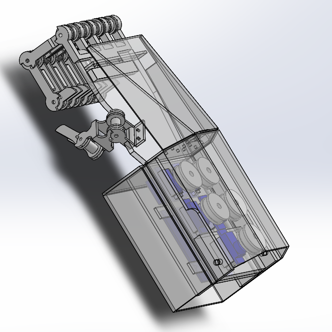
ITERATION 3:
- Link1 of all the fingers and thumb were redesigned to withstand higher forces.
- Assembly time was reduced by introducing holes in the pulleys and links.
- Protective casings were introduced.
- Servo motor connectors were introduced which enabled easy removal of servo motor.
- Wire connections were simplified and were made compact which eliminated the use of breadboard.
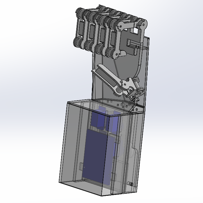
Fig 3: CAD Model Of Iteration 3.
Design Of Controller:
The fingers movements may either be controlled in a predefined manner by uploading the code in the Arduino or by manually operating the handgear consisting of controllers. There are in total 5 controllers each worn on one finger, the movement of the finger is transmitted from finger tip to the potentiometer in terms of rotation through the links. Rotation of potentiometer changes the resistance, which is input to the Arduino.
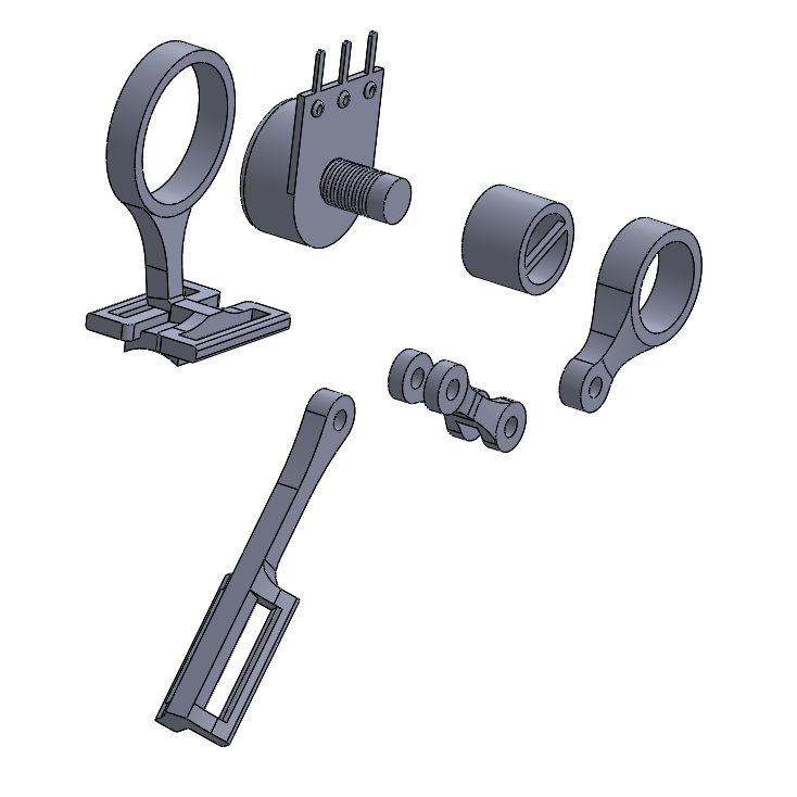
Fig 4: CAD Model of Controller(Exploaded View).
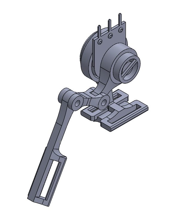
Fig 5: CAD Model Of Controller(Assembly).
Modes Of Control:
PIN ARRANGEMENT:
- 12 pins of robotic hand Arduino are used as input.
- Pin 2, 4, 6, 8, 10 are PWM pins which can also be used as digital pins.
- Pin 0, 1, 3, 5, 7, 9, 11 are digital pins.
- The pins can be made HIGH or LOW by using an external Arduino.
- The modes are selected by applying a HIGH==1 or LOW==0 signal to the Pin 0 and Pin 1.
There Are 4 Modes Of Control:
- Direct Binary Control (Mode 00).
- Direct Variable Control (Mode 01).
- 4-Point Potentiometer Control (Mode 10).
- Filtered Potentiometer Control (Mode 11).
Direct Binary Control (Mode 00):
- The mode pins 0,1 are both set to low in order to select this mode.
- The digital pins (3,5,7,9,11) and PWM pins (2,4,6,8,10) are all set to LOW.
- When the mode pins are set to LOW the pre written code gets executed as desired by the user.
- This is the simplest mode available and can only perform extreme flexion and extreme extension of finger/thumb.
Direct Variable Control (Mode 01):
- The mode pins 0 and 1 are set to LOW and HIGH respectively in order to select this mode.
- In this mode the intermediate positions of the finger/ thumb can also be achieved through improvement in the code.
- When this mode is selected the pre written code gets executed as desired by the user.
4-Point Potentiometer Control (Mode 10):
- The handgear is used in this mode. It has 12 outputs (i.e. from pin 2 to pin 13 of handgear Arduino Uno) which serve as inputs to the Arduino of robotic hand.
- Ideally a potentiometer rotates by approximately 270° and the Arduino reads this rotational change as values ranging from 0 to 1023.
- But during the flexion and extension process of the index finger the potentiometer of the controller will rotate by approximately 90°. The range detected by the Arduino in these 90° is 110 to 370.
- This range is then mapped to the range (10 to 170) using the C function in the coding process of Arduino. During the coding process the range (10 to 170) is divided into 4 parts and for each part, the allocated pins of the handgear attain certain HIGH/LOW values.
- Since the outputs of handgear pins serve as inputs to the robotic hand pins, the values of pins of handgear are transmitted to the pins of the robotic hand respectively.
Filtered Potentiometer Control (Mode 11):
- Unlike the 4-Point Potentiometer Control which traces only 4 angles, Filtered Potentiometer Control traces all the angles made by the user’s finger and hence has a higher accuracy.
- The handgear Arduino only serves as a mode selector and as a power supply to all the five potentiometers.
- The output from the controller potentiometers serves as the input to the robotic hand analog pins.
- The potentiometer values are then mapped to a suitable range and used in the coding process.
- Initially during the implementation of this mode, the robotic hand detected a lot of noise from the controller potentiometers. Hence a filtration code had to be introduced in the robotic hand Arduino to eliminate this noise. Therefore the name Filtered Potentiometer Control.
Fabrication:
Two prototypes were built of the robotic hand.
=> Initial Prototype.
=> Final Prototype.
Following are some images of the prototypes:
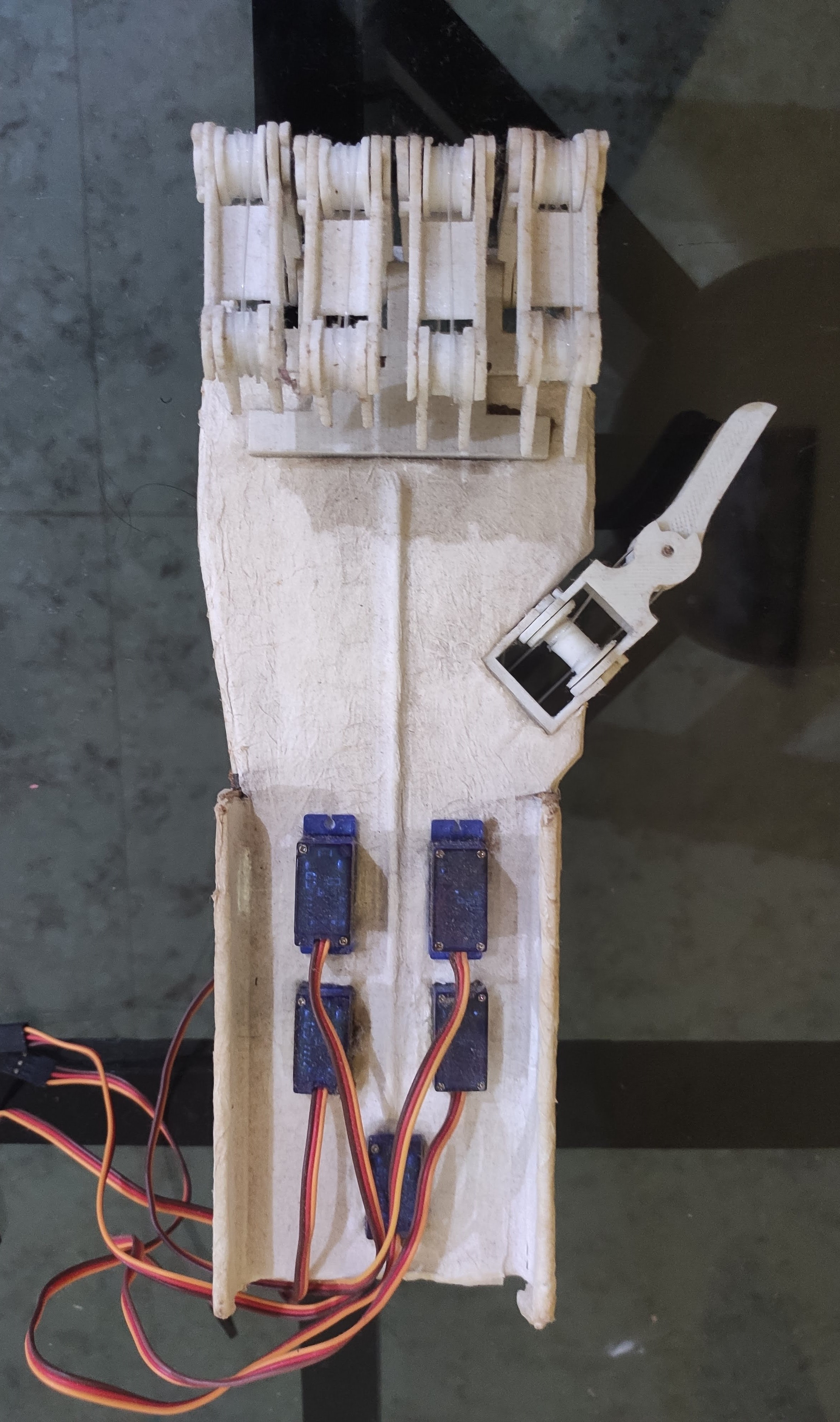
Fig 6: Initial Prototype(fig 1).
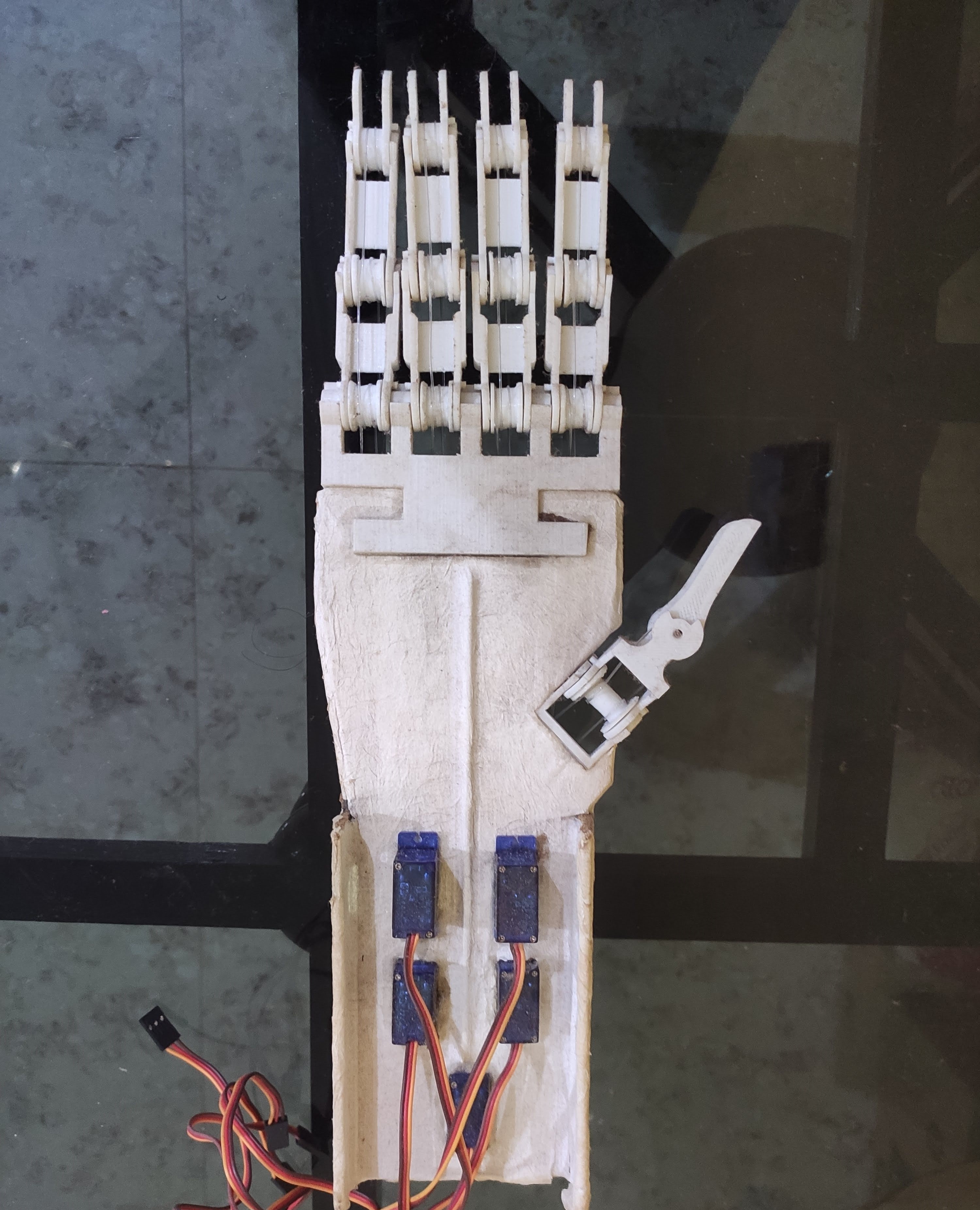
Fig 7: Initial Prototype(fig 2).
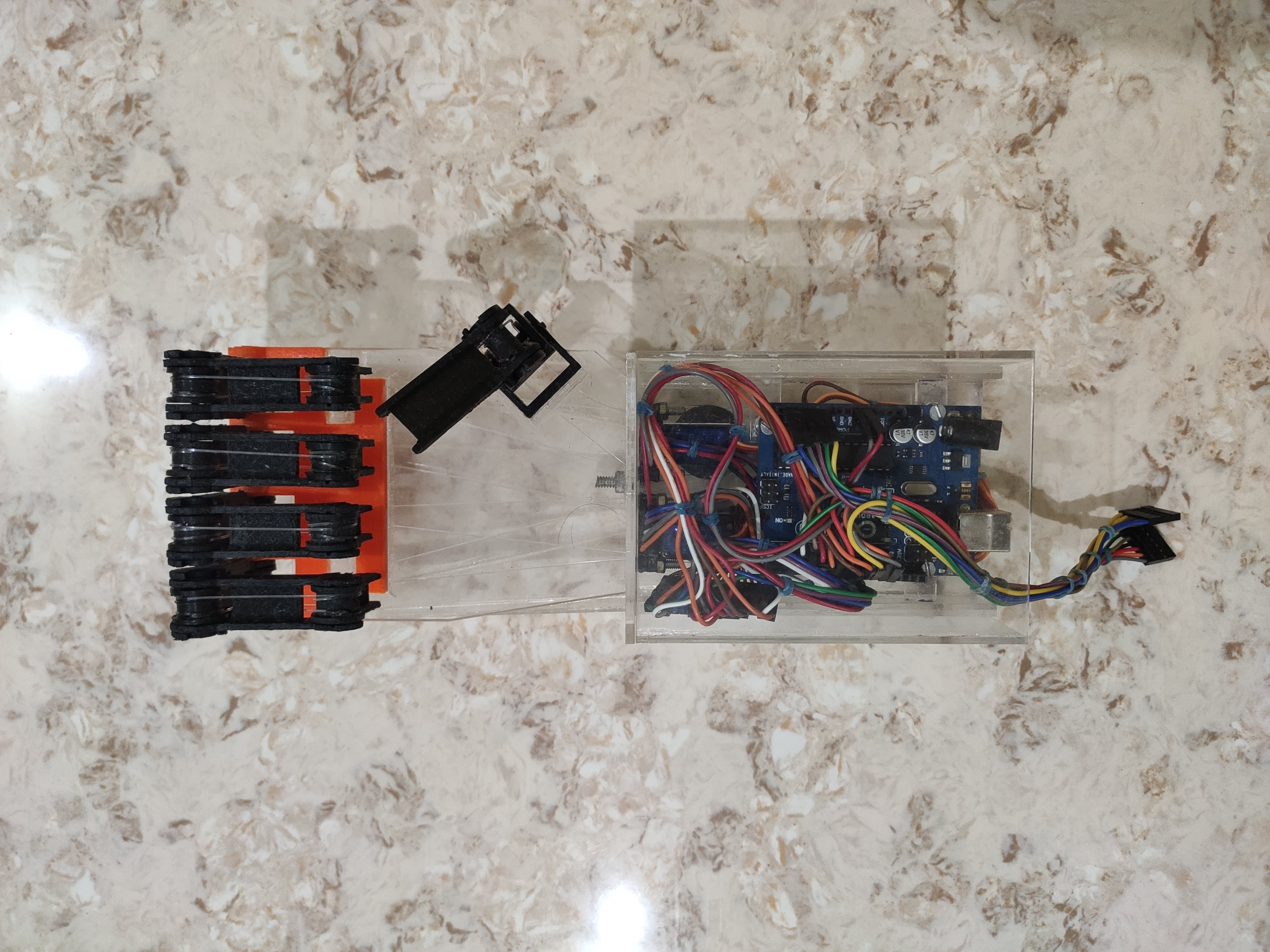
Fig 8: Final Prototype(fig 1).
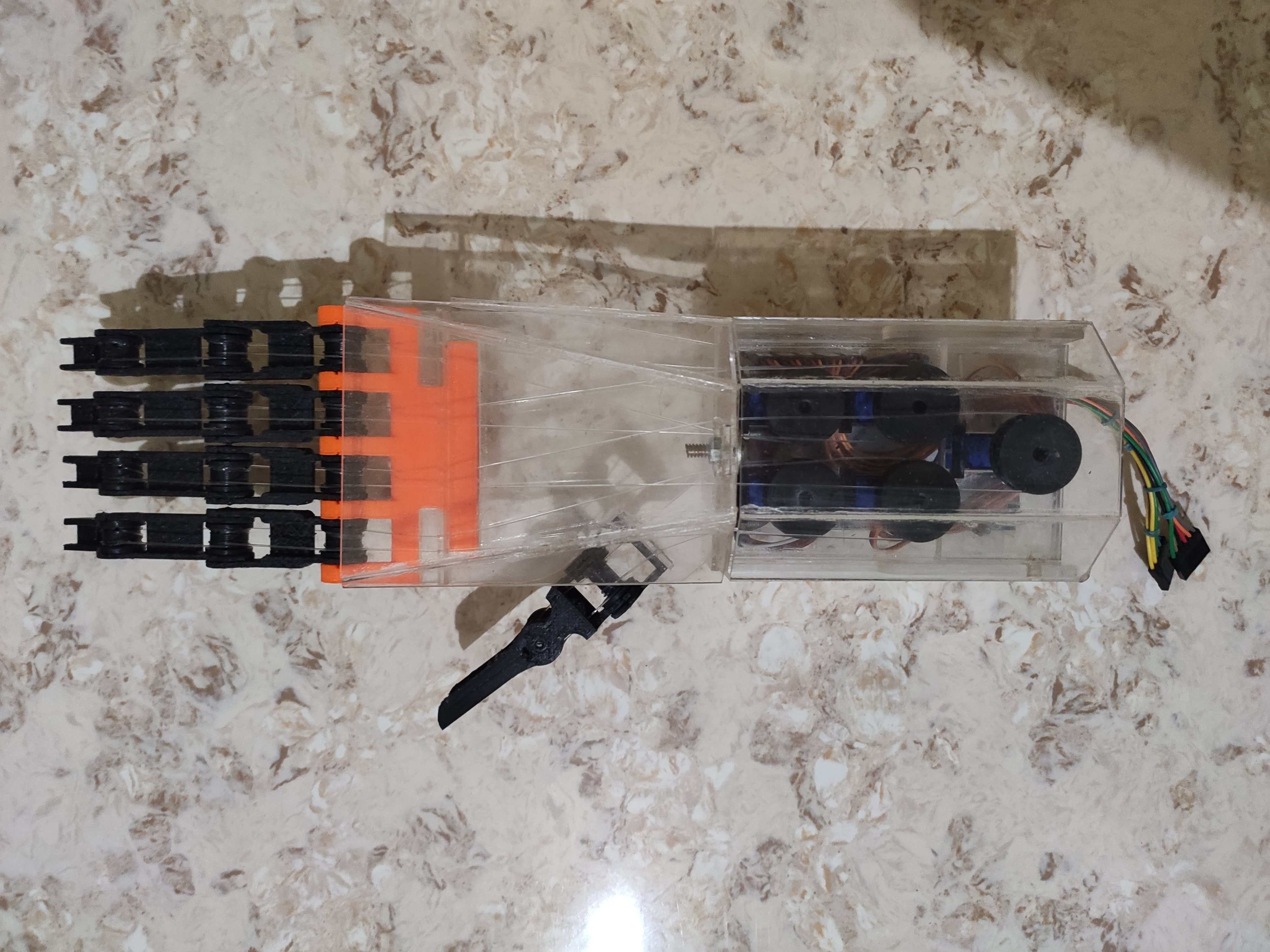
Fig 9: Final Prototype(Fig 2).
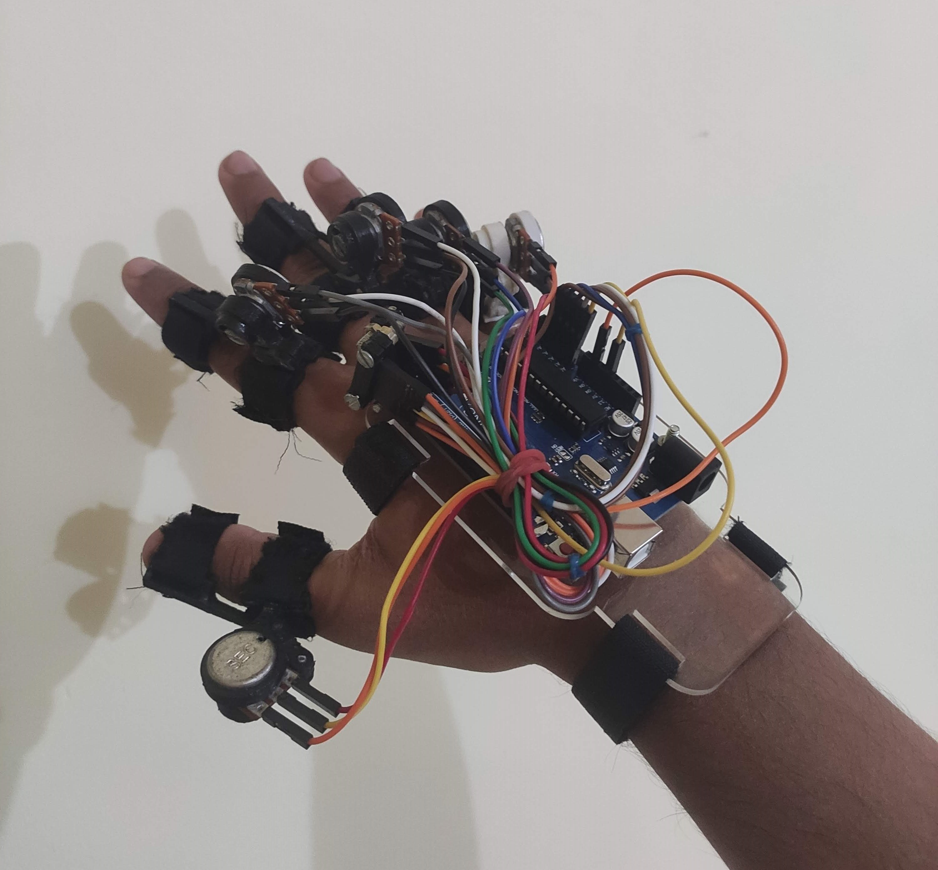
Fig 10: Handgear.
conclusion:
- Based on the performance of robotic hand, as seen in results section, the proposed anthropomorphic robotic hand can successfully grasp objects of different shapes.
- The four modes of control gave satisfactory results and robotic hand can successfully be controlled by handgear to mimic grasping motion of the operator.
- The robotic hand upon complete fabrication, resembled very close to human hand.
- Thus, it is concluded that an anthropomorphic robotic hand with simple design and minimal cost of fabrication can be developed to assist humans in performing various tasks.
Scope for future work:
- Increase in DOF leading to increase in dexterity.
- Movement of the wrist.
- High scope in advancement of control system.
- Tactile sensors can be used to provide force feedback.
- Flex sensors may be used instead of potentiometers.
- Use of bluetooth or wifi module for teleoperated.
- Improvement in strength and rigidity of the robotic hand.
- Further development into a complete arm.
Web Application Developed By MecKloid